DISC SPRINGS
Engineered for High Load Performance
SCHNORR® Disc Springs are designed to deliver exceptional force, reliability, and durability in compact installation spaces. Engineered to perform under extreme loads and dynamic operating conditions, they are trusted across industries including automotive, energy, heavy machinery, rail, and industrial manufacturing.
Manufactured with precision and consistent quality, SCHNORR® Disc Springs provide efficient load distribution, vibration resistance, and long service life for applications requiring dependable mechanical performance and safety.
Quick Facts
-
Linear or progressive load deflection characteristic.
-
Long and predictable service life with dynamic load.
-
Manufactured to DIN 16983 & DIN 16984
Features
Why engineers specify it
-
Efficient use of space providing high spring loads.
-
Can be combined in series or parallel configurations to customize load-deflection characteristics.
-
Largely self-dampening.
-
Presetting results in no setting under static loads
APPLICATIONS
Possible spring combinations:
-
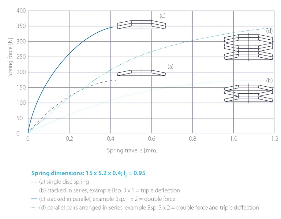
For series stacks, the deflections are additive at the same force (b).
-
For parallel stacks, the forces are additive at the same deflection (c).
-
For combination of series and parallel stacking, various characteristic curves can be realized (d).
DISC SPRING STACKS
Combine for any characteristic curve
-
A guide element is needed to prevent lateral movement.
-
Inside guidance on a bolt or shaft is preferred, although outside guidance is acceptable as well.
-
The guide elements and abutments should be hardened to a minimum of 60 HRC (minimum case depth of 0.8 mm), if possible.
-
The surface of the guide element should be smooth and, if possible, ground down.
-
For static applications, guides can be unhardened.
Materials
Engineered material options
Carbon Steel
Chrome Vanadium
Heat-Resistant Stainless
Corrosion-Resistant
Inconel
Tolerances
-
A guide element is needed to prevent lateral movement.
-
Inside guidance on a bolt or shaft is preferred, although outside guidance is acceptable as well.
-
The guide elements and abutments should be hardened to a minimum of 60 HRC (minimum case depth of 0.8 mm), if possible.
-
The surface of the guide element should be smooth and, if possible, ground down.
-
For static applications, guides can be unhardened.
Disc springs are manufactured to the following standards:
DIN EN 16983 – Quality requirements, Dimensions
DIN EN 16984 – Calculation
(Formerly DIN 2092- Calculation of Disc Springs and DIN 2093 – Quality requirements, Dimensions)
APPLICATIONS
The conical shape allows springs to be combined in different ways.
Possible spring combinations:
For series stacks, the deflections are additive at the same force (b).
For parallel stacks, the forces are additive at the same deflection (c).
For combination of series and parallel stacking, various characteristic curves can be realized (d).
DISC SPRING STACKS
A guide element is needed to prevent lateral movement.
Inside guidance on a bolt or shaft is preferred, although outside guidance is acceptable as well.
The guide elements and abutments should be hardened to a minimum of 60 HRC (minimum case depth of 0.8 mm), if possible.
The surface of the guide element should be smooth and, if possible, ground down.
For static applications, guides can be unhardened.
MATERIALS
Carbon Steel
C75S (1.1248)
per DIN EN 10132-4
Chrome Vanadium
per DIN EN 10151
Heat Resistant Stainless Steels
per DIN EN 10269 or 10088-2
Corrosion Resistant Steels
X7 CrNiAl 17-7 (1.4568)
per DIN EN 10151
Inconel
X750 (2.4669)
TOLERANCES
Disc springs are manufactured to the following standards:
DIN EN 16983 – Quality requirements, Dimensions
DIN EN 16984 – Calculation
(Formerly DIN 2092- Calculation of Disc Springs and DIN 2093 – Quality requirements, Dimensions)